Basic Info.
Model NO.
Beest ARP
Regenerated Acid Concentration
18%--20%
Energy
Natural Gas
Type
Fluidized Bed
by-Product
Fe2o3 Pellets
Reaction Temp.
850 Celsius
Transport Package
Container
Specification
300L/h -- 2000L/h
Trademark
Beest
Origin
China
HS Code
842121
Production Capacity
300L/H
Product Description
Waste HCl Acid Regeneration Equipment
Plant design data
| Waste Pickle liquor | l/h | 300 |
| Fe2+ Content | g/l | ~120 |
| Fe3+ Content | g/l | 0 |
| Total HCl Content | g/l | ~200 |
| Free HCl Content | g/l | ~40 |
| Rinse Water | l/h | ~320 |
| Fe2+ Content | g/l | 3 |
| Fe3+ Content | g/l | - |
| Total HCl Content | g/l | ~13 |
| Regenerated Acid | l/h | ~350 |
| Total HCl Concentration | g/l | 196 |
| Total Fe Content | g/l | 3 |
| Oxide | kg/h | 52 |
Process Description
The chemical process of steel pickling, where scale is removed from the steel surface, can be expressed in the following simplified equation:

Pickling reaction: FeO + 2HCl== FeCl2 + 2H2O
The process of recycling the waste acid, discharged from the pickling line, is based on the Pyrohydrolysis reaction:
Regeneration: 2FeCl2 + 2H2O + ½O2==Fe2O3 + 4 HCl
Chemistry of the Acid Recovery Process
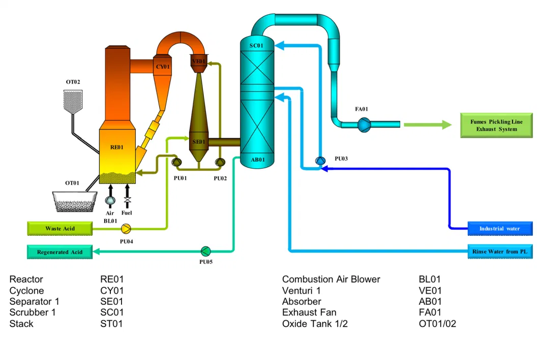
The recovery of the HCl for reuse in the pickling process, takes place in the Reactor.
The fluidized bed process uses an oxide pellet bed, which is formed by the chemical reaction of waste acid with the reactor gas. The chemical reaction takes place at 850°C and all the oxide produced forms new layers on the oxide product. Removing the oxide from the reactor and adding fines into the reactor can control the pellet size.
VENTURI CIRCULATION SYSTEM
The waste acid (WA) from the pickling line enters the separator SE01 of the regeneration plant.
The liquids from the separator are pumped into the Venturi VE01, where a direct cooling of the hot reactor off gases takes place.
The liquids are vaporized and the hot gases cool down to an average temperature of approx. 100 °C.
As part of the liquids, mainly water, vaporizes, the concentration of metal chloride in the circulating venturi-liquids increases. This increase of concentration is tracked and controlled by measuring the density of the circulating liquid.
By using this direct cooling system, a very high heat exchange rate and removal of dust and soluble gas components can be achieved.
The control of the level and the Fe-concentration in the so called venturi circuit is performed by automatic control system PLC and provides constant recovery conditions.
REACTOR-CYCLONE:
A partial amount of pre-concentrated WA is feed via a separate pump through a lance into the reactor RE01.
Here the reactions to hydrogen chloride and metal oxide take place at homogenous temperature around 800°C.
The metal chlorides solution injected into the fluidized bed form Metal Oxides, which settle down on the bed material and build up the seed granules in an onion-like layer shape, up to approx. 1 mm diameter before they are removed from the reactor.
Fine particles of oxide entrained in the gas stream from the reactor are separated by the cyclone CY01 and returned back to the reactor
The gas leaving the cyclone passes through the venturi for cooling
OXIDE HANDLING:
The oxide pellets, which are formed inside the fluidized bed are automatically discharged from the Reactor into the oxide tank OT01.
The oxide consists of dust free pellets. A part of the oxide pellets is separated into the startup tank OT02 for the filling of the reactor after during the next startup.
ABSORBER
In the absorber AB01 the regenerated acid is produced. Rinse water, which is sprayed onto the packing inside AB01 absorbs the gaseous HCl. The produced regenerated acid has a concentration of approx. 18%w/w.
SCRUBBER
Downstream of the Absorber a scrubber SC01 is installed in order to further remove HCl from the off gas. This is done by circulating the washing liquid in order to reach a higher liquid load and to increase the efficiency of the scrubber.
The washing water is cooled down using a heat exchanger. By doing so the fumes can be cooled down to below 50°C. This will condense most of the water in the fumes and reducing the amount of fumes to ca. 50%. This operation ensures low emission figures and almost no visual plume in the stack.
EXHAUST FAN
The exhaust fan FA01 transports the off gases and keeps the entire system under a negative pressure. This ensures the tightness of the system so that no fumes can escape.
After the fan the fumes enter the stack and go to the ambient.
FINAL TREATMENT
Finally, the fumes will be lead to the Fume Exhaust System of the pickling Line. The fumes will be treated together with the fumes of the pickling line. This ensures the required emission limits, while reducing the investment cost to a minimum.


